Using Scripts for Topological Analysis
Scripts are able to automate the various topological analysis functions provided by Bentley Map and also adds a few more topological functions to the basic Bentley Map capabilities.
The spatial analysis functions work by having one script calling another script using a spatial operator. The topological analysis functions work by manipulating elements on a topological layer using special functions. The spatial analysis functions can only analyze existing elements whereas the topological analyses can also create new elements as the result of the topological analysis.
Each topological layer has a unique logical name. The name can consist of letters and numbers and be up to 40 characters long.
When creating a new empty topological layer, its type must be defined: POINT, LINE or POLYGON. It is not possible to mix the types of graphical elements in a topological layer. A POINT type topological layer can only store points, such as texts, text nodes or zero-length lines.
|
Layer type |
Valid design file types |
|
POINT |
Text, Text Node, zero-length Line |
|
LINE |
Line, Line String, Complex String, Arc, B-spline, Curve |
|
POLYGON |
Shape, Complex Shape, Grouped hole cells are valid for defining the area. For defining the centroid points, use POINT type elements. For defining the boundary linework, use LINE type elements. |
When using a topological function to create a new layer from existing layers, the new layer inherits the proper layer type.
POLYGON layers not only contain the actual areas, but also the boundary linework and the centroid points. Most topological functions use the boundary linework and centroid points, and the actual areas must be recreated afterwards using the TOPO CREATE AREA function.
When adding design file elements to a topological layer, the graphical element is transformed into an internal representation consisting of node points and vertices, which is more suitable for doing fast topological analysis. In order to store the result of a topological analysis in the design file, simply use TOPO RAINBOW with the /ADD qualifier.
To change the symbology, feature, etc., write a special script using SETUP LAYER to process only graphical elements on the specified topological layer. After setting the proper variables, use the PLACE ELEMENT command to store the element in the design file.
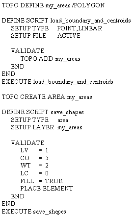
Example: This example loads lines and centroid points, builds areas, and saves the result as filled shapes or complex shapes in the design file.